Table of Contents
ToggleIntroduction
Pneumatic cylinders are the workhorses of industrial automation, powering countless machines with clean, efficient, and reliable motion. But how exactly does a pneumatic cylinder transform compressed air into precise linear movement? The answer involves an elegant interplay of physics, mechanical design, and fluid dynamics—all orchestrated to deliver controlled force with remarkable simplicity.
At its core, a pneumatic cylinder operates on the principle of differential pressure. Compressed air enters the cylinder, acting upon a piston, which converts this pressure into kinetic energy. However, this process is far more nuanced than it first appears. Variables like bore size, stroke length, and valve response time all influence the cylinder’s performance. Understanding these mechanisms is critical for engineers designing automation systems, maintenance technicians troubleshooting failures, or procurement specialists selecting the right model for an application.
This article delves deep into the mechanics of pneumatic cylinders, breaking down every stage—from air intake to motion output—with real-world analogies, technical diagrams, and best-practice insights. Whether you’re troubleshooting a slow-acting cylinder or optimizing a high-speed assembly line, this guide equips you with the knowledge to master pneumatic motion.
1. What Are the Core Components of a Pneumatic Cylinder?
1.1 Cylinder Barrel
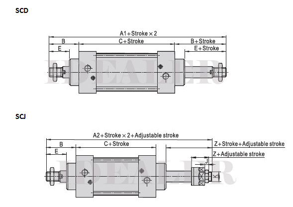
The barrel is a precision-machined tube that houses the piston and provides a sealed pathway for linear motion. Made from materials like stainless steel or aluminum, it must balance durability with smooth internal finishing to minimize friction.
1.2 Piston and Piston Rod
The piston divides the cylinder into two chambers (advance and retract). When pressurized air enters one side, it pushes the piston, which transmits force via the rod. Rods are typically hardened steel to resist bending and wear.
1.3 Seals and Cushioning
Dynamic seals prevent air leakage while allowing smooth piston movement. Advanced cylinders feature built-in cushioning (e.g., adjustable air dampers) to decelerate the piston at stroke endpoints, reducing impact noise and wear.
1.4 Ports and Valves
Air enters and exits through ports connected to solenoid valves. Fast-acting valves (5/2 or 5/3-way) control directional flow, ensuring rapid response times for high-cycle applications.
1.5 End Caps and Mounting
End caps seal the barrel and often integrate mounting features (e.g., flange, clevis). Proper mounting ensures alignment and absorbs thrust forces.
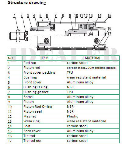
(Table: Common Cylinder Materials and Their Applications)
| Material | Advantages | Typical Use Cases |
|---|---|---|
| Aluminum | Lightweight, corrosion-resistant | Packaging, electronics |
| Stainless Steel | High strength, chemical resistance | Food processing, pharmaceuticals |
| Nickel-plated Brass | Excellent wear resistance | Marine, high-humidity environments |
2. How Does Compressed Air Generate Linear Force?
At the heart of every pneumatic system lies a simple but profound question: How does something as intangible as compressed air produce the powerful, precise linear motion that drives industrial automation? The answer combines fundamental physics with clever mechanical engineering—and it all starts with understanding how air pressure translates into real, measurable force.
This section breaks down the exact mechanisms behind pneumatic force generation, from the universal laws of fluid dynamics to practical calculations engineers use daily. Whether you’re selecting cylinders for a new assembly line or troubleshooting weak actuator performance, these principles form the bedrock of pneumatic system mastery.
2.1 Pascal’s Law in Action: The Foundation of Pneumatic Force
The Physics Behind the Power
Pneumatic cylinders operate on Pascal’s Principle, formulated by Blaise Pascal in 1653. This fundamental law states:
“Pressure applied to a confined fluid transmits uniformly in all directions without loss.”
In practical terms, when compressed air enters a sealed cylinder chamber, every square millimeter of the piston surface experiences equal pressure. This uniformity ensures predictable, repeatable force output—critical for industrial automation.
Force Calculation: The Core Equation
The linear force (F) generated by a pneumatic cylinder is derived from:
F = P × A
Where:
- F = Force (Newtons or lbf)
- P = Pressure (Pascals or psi)
- A = Effective Piston Area (m² or in²)
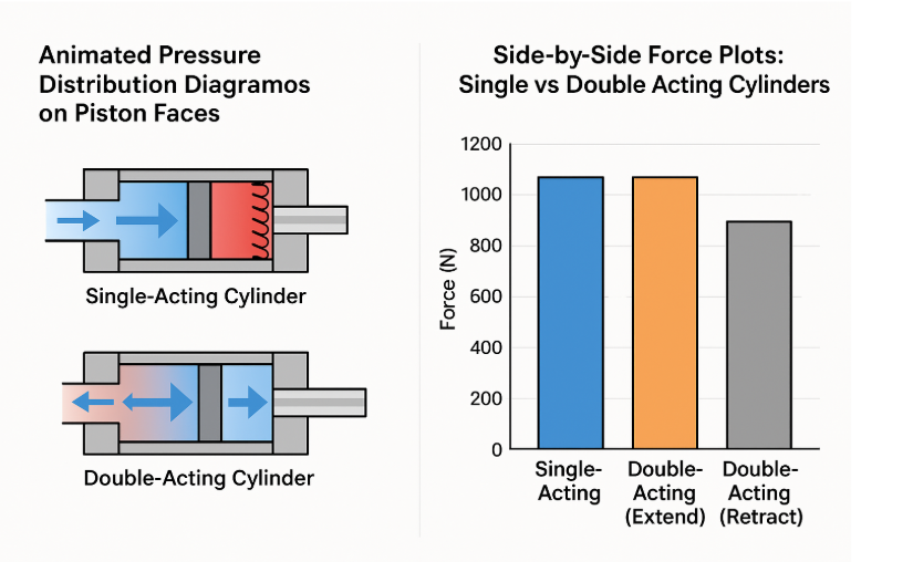
For a double-acting cylinder, the effective area differs between extension and retraction strokes due to the piston rod occupying space on one side:
- Extension (Push) Force: Uses full piston area (A = π × (Bore Diameter/2)²)
- Retraction (Pull) Force: Subtract rod area (A = π × [(Bore/2)² − (Rod Diameter/2)²])
(Table: Common Pressure Units for Pneumatic Calculations)
| Unit | Definition | Conversion to PSI |
|---|---|---|
| Bar | 100,000 Pascals | 1 bar = 14.5 psi |
| PSI | Pounds per Square Inch | — |
| kPa | Kilopascals (1,000 Pascals) | 6.895 kPa = 1 psi |
Real-World Implications
- Higher Pressure = More Force, but Diminishing Returns: Doubling pressure doubles force, but also increases energy costs and heat generation.
- Bore Size Trade-offs: A larger bore amplifies force (area grows squared with diameter), but demands more air volume, slowing cycle times.
2.2 Pressure Differential and Motion: The Stroke Cycle Explained
Double-Acting Cylinder Operation
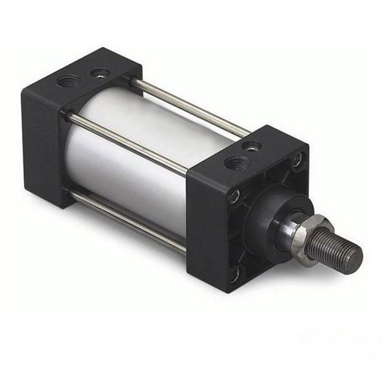
A double-acting cylinder alternates airflow between two ports to produce bidirectional motion. Here’s the step-by-step sequence:
Extension Stroke (Pushing Force)
- Air Supply: Pressurized air enters the rear port via a 5/2-way solenoid valve.
- Exhaust Path: The front port vents to atmosphere (or through a muffler).
- Force Generation: Pressure acting on the full piston area drives the rod outward.
Retraction Stroke (Pulling Force)
- Valve Shifts: The solenoid valve switches states, routing air to the front port.
- Exhaust Reversal: The rear port now vents while the front pressurizes.
- Reduced Force: With the rod occupying part of the piston area, retraction force is typically 10–25% weaker than extension (for same pressure).
Single-Acting Cylinder Variations
- Spring Return: Compressed air extends the piston; a mechanical spring provides retraction force.
- Force Imbalance: The spring must be overcome during extension (F_net = P×A − Spring Force).
- Applications: Low-cost, failsafe systems (e.g., emergency clamps).
2.3 Calculating Force Output: From Theory to Practice
Step-by-Step Example (50mm Bore @ 6 bar)
Let’s compute the extension force for a standard industrial cylinder:
Convert Pressure to Pascals:
- 6 bar = 600,000 Pascals (1 bar = 100,000 Pa)
Calculate Piston Area (A):
- Bore Diameter (D) = 50 mm = 0.05 m
- Radius (r) = D/2 = 0.025 m
- Area (A) = π × r² = 3.1416 × (0.025)² ≈ 0.001963 m²
Compute Force (F):
- F = P × A = 600,000 Pa × 0.001963 m² ≈ 1,178 Newtons
- Convert to Pounds-force (lbf): 1 N = 0.225 lbf → 1,178 × 0.225 ≈ 265 lbf
Critical Adjustments for Real-World Accuracy
- Efficiency Losses: Actual force is ~85–95% of theoretical due to:
- Seal friction (2–5% loss)
- Valve/flow restrictions (5–10%)
- Dynamic Effects: High-speed applications see inertial losses during acceleration/deceleration.
(Table: Sample Force Outputs at 6 bar)
| Bore (mm) | Theoretical Force (N) | Real-World Force (N)* |
|---|---|---|
| 20 | 188 | 160–180 |
| 32 | 483 | 410–460 |
| 50 | 1,178 | 1,000–1,120 |
| 80 | 3,016 | 2,560–2,865 |
| *Assumes 85–95% efficiency |
Advanced Considerations
- Cushioning Force: Deceleration at stroke ends briefly spikes pressure (add 10–20% safety margin).
- Rod Buckling: Long-stroke cylinders require force calculations to avoid rod bending (Euler’s formula).
3. What Factors Influence Motion Precision and Speed?
Pneumatic cylinders are prized for their rapid response and simplicity, but achieving consistent speed and positioning accuracy requires careful attention to system design. From airflow dynamics to mechanical loading, multiple variables can turn a theoretically efficient system into one plagued by hesitation, overshooting, or uneven motion.
This section dives deep into the engineering considerations behind pneumatic motion control—breaking down how valve selection, load management, and deceleration techniques work together to create smooth, repeatable movement. Whether you’re optimizing a pick-and-place robot or troubleshooting jerky actuator performance, these principles form the blueprint for precision.
3.1 Air Flow and Valve Sizing: The Gatekeepers of Speed
Flow Rate (Cv) and Its Impact on Performance
Every pneumatic valve is rated by its flow coefficient (Cv), defined as:
The volume of water (in gallons per minute) that flows through a valve at 1 psi pressure drop.
For pneumatic systems, this translates to airflow capacity. An undersized valve becomes a bottleneck, limiting cylinder speed regardless of pressure.
Calculating Required Cv
To match a valve to your cylinder:
Cv = (Q × 60) / (963 × ΔP × SQRT(ΔP × (P1 + 1.013)))
Where:
- Q = Airflow demand (L/s)
- ΔP = Permissible pressure drop (bar)
- P1 = Inlet pressure (bar absolute)
Example: A 50 mm bore cylinder with 300 mm stroke at 6 bar requires ~40 L/s airflow for 0.5 m/s speed. At ΔP=0.3 bar, this demands a valve with Cv ≥ 1.2.
(Table: Cv Requirements for Common Cylinder Sizes)
| Bore (mm) | Speed (m/s) | Required Cv (ΔP=0.3 bar) |
|---|---|---|
| 25 | 0.8 | 0.5 |
| 50 | 0.5 | 1.2 |
| 100 | 0.3 | 4.0 |
Valve Response Time: Electromechanical Delay
- Direct-Acting Solenoids: Use electromagnetic force to shift the spool (15–50 ms response).
- Pilot-Operated Valves: Use air pressure to assist switching (<10 ms response).
- Critical for high-cycle applications (>5 Hz).
Pro Tip: For ultra-fast cycles, use piezoelectric valves (1–2 ms response) despite higher cost.
3.2 Load and Friction Effects: The Enemies of Smooth Motion
Overcoming Inertia
Newton’s First Law dictates that heavier loads resist acceleration/deceleration more strongly. The required force to move mass m at acceleration a is:
F = m × a
Practical Implications:
- Doubling load mass requires either:
- Higher pressure (but risks seal damage if over 10–12 bar).
- Larger bore cylinder (increases air consumption).
- Rule of Thumb: For loads >50 kg, consider servo-pneumatics for controlled acceleration ramps.
Stiction (Static Friction): The Silent Killer
Caused by:
- Dry seals (lack of lubrication).
- Misaligned rod/load couplers.
- Poor surface finish on piston rods.
Symptoms:
- Jerky initial movement (“stick-slip” effect).
- Inconsistent stop positions (±2–5 mm variance).
Solutions:
- Use self-lubricating seals (PTFE-based).
- Install rod guides to prevent side loading.
- Apply slow-start valves to gradually overcome stiction.
3.3 Cushioning and Deceleration: Stopping on a Dime
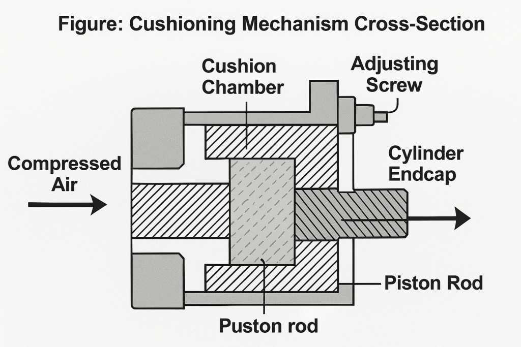
Adjustable Cushions (Integrated Dashpots)
Most cylinders have end-of-stroke cushions that:
- Trap air in a small chamber as piston approaches the end.
- Gradually increase backpressure to decelerate the load.
Tuning Guidelines:
- Start with cushions 1/2 turn open; adjust until impact noise disappears without excessive cycle time increase.
- For heavy loads (>50 kg), combine with external shock absorbers.
External Shock Absorbers
Necessary when:
- Speeds exceed 1 m/s.
- Loads >100 kg must stop in <50 mm.
Selection Criteria:
- Energy Absorption (Joules): Must exceed kinetic energy (0.5×m×v²).
- Cycle Life: Oil-free absorbers last longer in dirty environments.
Speed vs. Bore Size: The Trade-Off Table
Compression speed inherently decreases with larger cylinders due to greater air volume demands. Here’s how typical industrial cylinders perform at 6 bar:
(Table: Speed vs. Bore Size at 6 bar)
| Bore (mm) | Speed Range (m/s) | Max Load (kg) | Air Consump. (L/cycle) |
|---|---|---|---|
| 25 | 0.5–1.0 | 20 | 0.15 |
| 50 | 0.3–0.8 | 80 | 0.60 |
| 100 | 0.2–0.5 | 300 | 2.35 |
Key Insight: Smaller bores accelerate faster but lack force; larger bores provide power at the cost of speed.
Practical Optimization Checklist
- Valve Sizing: Ensure Cv meets airflow demand; prioritize pilot-operated valves for >3 Hz cycling.
- Load Management: For inertial loads, use larger bores or multi-stage acceleration profiles.
- Friction Mitigation: Lubricate rods, align load paths, and consider low-friction seals.
- Deceleration: Tune cushions iteratively; add shock absorbers for high-mass/high-speed moves.
4. How Do Different Cylinder Designs Affect Performance?
Choosing the right pneumatic cylinder design directly impacts force output, motion precision, energy efficiency, and system longevity. From single-acting spring-return cylinders to sophisticated rodless or multi-stage telescopic models, each variant serves unique industrial needs. This section explores key cylinder types, their performance trade-offs, and how to match them to real-world applications.
4.1 Single-Acting vs. Double-Acting Cylinders
The choice between single-acting and double-acting cylinders hinges on force requirements, stroke control, and energy efficiency.
➤ Single-Acting Pneumatic Cylinders
Working Principle:
- Compressed air enters only one chamber (typically the rear), extending the piston.
- A built-in mechanical spring retracts the piston when air pressure is released.
Advantages:
- Simpler Design: Fewer seals and no need for dual air supply lines, reducing cost and maintenance.
- Failsafe Retraction: Spring ensures automatic return if air supply fails (critical in safety applications).
Limitations:
- Reduced Force Output: Spring force opposes extension, requiring higher air pressure for the same net output.
- Limited Stroke Length: Springs lose effectiveness beyond ~100 mm due to fatigue risks.
- Lower Speed: Spring retraction is slower than pneumatic actuation.
Typical Uses:
- Clamping, light-duty presses, emergency brakes.
- Low-cost automation where unidirectional force suffices.
➤ Double-Acting Pneumatic Cylinders
Working Principle:
- Air pressure alternates between both chambers (front and rear) for bidirectional force.
- No internal spring; retraction relies on air pressure alone.
Advantages:
- Higher Force & Speed: Full air pressure drives both strokes, enabling faster cycles.
- Precise Mid-Stroke Positioning: Proportional valves allow controllable stopping points.
- Longer Stroke Feasibility: No spring limitations (strokes up to 2,000+ mm).
Limitations:
- Complex Plumbing: Requires a 4/2 or 5/2-way valve for directional control.
- No Failsafe Retraction: Requires external valves for safety positioning in power loss scenarios.
Typical Uses:
- Robotics, CNC tool changers, heavy lifting.
- Applications demanding consistent bidirectional force.
(Table: Single-Acting vs. Double-Acting Comparison)
| Factor | Single-Acting | Double-Acting |
|---|---|---|
| Force Output | Lower (spring opposition) | Higher (full air both ways) |
| Stroke Length | ≤100 mm (spring limits) | Up to 2,000+ mm |
| Energy Use | Lower (air for one stroke) | Higher (dual air demand) |
| Fail-Safe | Auto-retracts on air loss | Requires external safety |
| Cost | Lower (simpler design) | Higher (more components) |
4.2 Rodless Cylinders: Magnetic, Cable, and Band-Driven Designs
Rodless cylinders eliminate the traditional piston rod, offering compact linear motion ideal for tight spaces or long strokes. Three primary technologies dominate:
➤ Magnetic Coupling (Sliding Seal-Free)
How It Works:
- Internal piston carries magnets that couple with an external carriage.
- No physical rod; the carriage moves via magnetic attraction through the cylinder wall.
Advantages:
- Zero External Leakage: No sliding seals, ideal for cleanrooms or vacuum environments.
- Low Friction: Smoother motion than mechanical rod designs.
Limits:
- Lower Force Capacity: Magnetic coupling strength limits max load (~300 N typical).
- Temperature Sensitivity: Demagnetization risk above 80°C.
➤ Cable-Driven Cylinders
How It Works:
- Internal piston pulls a stainless-steel cable loop anchored to an external shuttle.
- Pulleys at cylinder ends redirect cable motion linearly.
Advantages:
- Long Strokes (Up to 10m): Cables flex better than rigid rods.
- No Stick-Slip: Minimizes stiction for precise starts/stops.
Limits:
- Cable Wear: Requires periodic replacement in high-cycle uses.
➤ Band or Profile-Guided Rodless
How It Works:
- A slotted aluminum profile barrel houses a piston connected to a guided carriage.
- Sealed bands cover the slot to prevent contamination.
Advantages:
- High Rigidity: Handles side loads better than cable/magnetic types.
- IP65+ Protection: Common in dusty/wet environments (e.g., food processing).

4.3 Telescopic and Multi-Position Cylinders: Extended Reach Solutions
➤ Telescopic Cylinders
Design:
- Nested piston stages extend sequentially (like a telescope).
- Multi-stage variants (2–6 stages) compactly achieve strokes 3× body length.
Performance Notes:
- Force Drops per Stage: Each extending stage reduces force due to smaller piston areas.
- Stability Challenges: Requires guided rails for lateral loads.
Applications:
- Dump trucks, scissor lifts, long-reach material handlers.
➤ Multi-Position Cylinders
How They Work:
- Multiple pistons in one barrel allow independent positioning (e.g., 3 pistons = 8 position combinations).
- Logic valves sequence air supply to selected chambers.
Uses:
- Packaging machines (adjustable stops), tool changers with discrete positions.
(Table: Telescopic vs. Multi-Position Features)
| Feature | Telescopic | Multi-Position |
|---|---|---|
| Stroke Gain | 3–6x body length | Fixed strokes per piston |
| Force Curve | Decreases with extension | Constant per active piston |
| Complexity | Moderate (mechanical stages) | High (valve sequencing logic) |
Key Takeaways for Cylinder Selection
- Force & Speed: Double-acting > single-acting; rodless types trade power for compactness.
- Env. Resistance: Band-guided rodless excels in harsh conditions.
- Stroke Needs: Telescopic for reach; multi-position for programmable stops.
5. Real-World Applications and Troubleshooting
Understanding how pneumatic cylinders perform in real-world industrial settings—and how to solve common problems—helps engineers optimize system performance and minimize downtime. Below, we examine high-performance applications, typical failure modes, and practical fixes.
5.1 High-Speed Automation: Where Pneumatic Cylinders Excel
Pneumatic cylinders play a critical role in fast, repeatable automation processes. Here are some key use cases:
5.1.1 Pick-and-Place Robots (Micron-Level Precision)
- Technology Used: Servo-pneumatic cylinders with proportional valves for dynamic force & speed control.
- Why Pneumatics? Faster acceleration than electric actuators (up to 10 m/s²) and immune to electromagnetic interference.
- Industry Example:
- Pharmaceutical Packaging – Vacuum grippers + rodless cylinders move vials at 200 cycles/min with ±0.1mm repeatability.
- Electronics Assembly – Guided cylinders with linear guides place SMD components at 1,200 parts/hour.
Table: Performance Comparison – Electric vs. Pneumatic in High-Speed Automation
| Metric | Pneumatic Actuators | Electric Actuators |
|---|---|---|
| Maximum Speed | 1.5 m/s | 0.5 m/s |
| Acceleration | 10 m/s² | 5 m/s² |
| Duty Cycle | 100% (Cooling via exhaust) | Requires cooldown |
| Cost (for 250N force) | $200–$500 | $800–$2,500 |
5.1.2 Pressing & Punching Applications
- Challenge: Avoiding “bounce” during high-speed stamping.
- Solution: Cushioned cylinders with adjustable shock absorbers reduce impact by 70%.
5.1.3 Packaging Lines (Bottle Cap Application)
- Problem: Inconsistent torque due to air pressure fluctuations.
- Fix: Pressure regulators with digital feedback maintain ±1% pressure stability.
5.2 Common Failures and Proven Fixes
5.2.1 Slow or Weak Movement (Most reported issue in Bosch Rexroth surveys)
- Root Causes:
✅ Clogged filters (Replace every 3–6 months in dusty environments)
✅ Undersized tubing (Upgrade to ≥1.5x port diameter for flow balance)
✅ Leaking seals (Check for hissing sound; replace polyurethane seals every 500K cycles)
5.2.2 Cylinder Chatter / Sticking
| Symptom | Likely Cause | Immediate Action | Long-Term Fix |
|---|---|---|---|
| Jerky motion | Dry/worn rod seals | Apply PFPE lubricant | Replace wiper + rod seal |
| Mid-stroke halt | Bent piston rod (≥0.1mm/m) | Inspect with dial indicator | Install guided cylinder |
| Uneven speed | Contaminated air (H₂O/Oil) | Drain auto-condensate valves | Add coalescing filter |
5.2.3 Air Consumption Spikes
- Diagnosis: Monitor SCFM using a flow meter. A 20%+ increase suggests:
- Leaking valve spool (Test with soap bubbles at exhaust ports)
- Damaged cylinder cushion (Locknut loosening is common after 2M cycles)
Conclusion
Pneumatic cylinders epitomize elegant engineering—harnessing air pressure to deliver repeatable, maintenance-free motion. By mastering the principles outlined here, you can optimize everything from actuator selection to troubleshooting.
Ready to Specify a Cylinder? Contact Our Engineering Team

