
Pneumatic fittings are small parts with big consequences: a missed tolerance or ambiguous thread callout can turn into leaks, galling, or line stoppages. Whether you’re matching a legacy part by sample or releasing a new design from an engineering print, getting the drawing package right is the difference between smooth production and costly rework with Chinese pneumatic manufacturers.
To customize pneumatic fittings, submit a physical sample or a controlled drawing that clearly defines geometry, material/grade, thread standard (BSPP/BSPT, NPT, ISO/metric), seals, plating, and inspection criteria. Suppliers typically accept STEP/IGES for 3D and DWG/DXF/PDF for 2D; include general tolerances (e.g., ISO 2768-m), GD&T for critical features, O‑ring groove notes (ISO 3601), and sealing face roughness. Attach an inspection plan with pressure/leak tests, sampling level, and accept/reject criteria.
In this guide, we’ll walk through what to include for threads, seals, and plating; which CAD formats your supplier can use; how to mark critical and geometric tolerances; and the inspection plan that should accompany your submission to Chinese pneumatic component manufacturers.
What drawing information must I include for threads, seals, and plating?
Getting the specification notes right ensures your supplier manufactures to the intended fit, function, and durability.
Clearly call out thread standards (BSPP/BSPT, NPT, ISO/metric) with size and class, define seal interfaces (O‑ring size/material, groove standard), and specify material and plating with thickness. Add pressure rating, media compatibility, and surface roughness requirements for leak-tight assembly.
Threads and connection details
- Thread standard and size:
- NPT: e.g., 1/4‑18 NPT; include taper, gauge limit notes if required
- BSPT/BSPP: e.g., G1/4 (BSPP, parallel) or R1/4 (BSPT, taper)
- ISO/metric: e.g., M10x1; include tolerance class (6H internal / 6g external)
- Thread features:
- Chamfer start angle (e.g., 45°)
- Thread reliefs/undercuts where applicable
- Seal type at thread: bonded seal, thread sealant requirement (PTFE tape not applied; liquid sealant to be specified if needed)
- Verification note:
- “Threads per standard; no burrs; go/no-go gauge acceptance required”
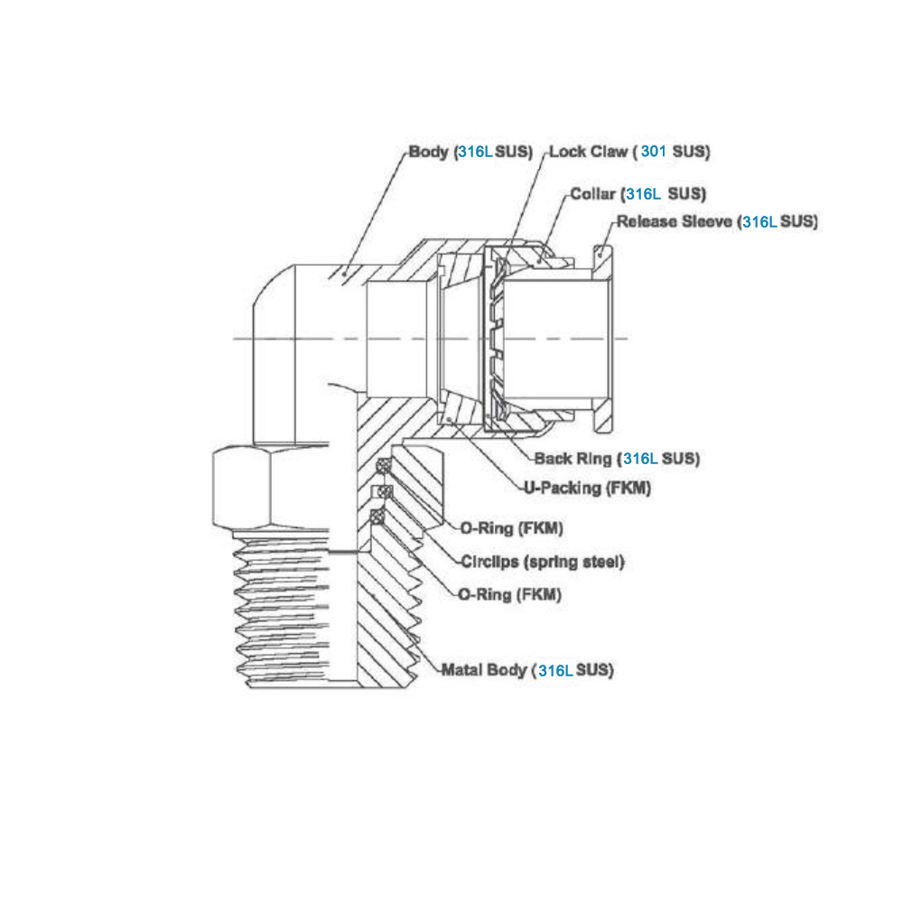
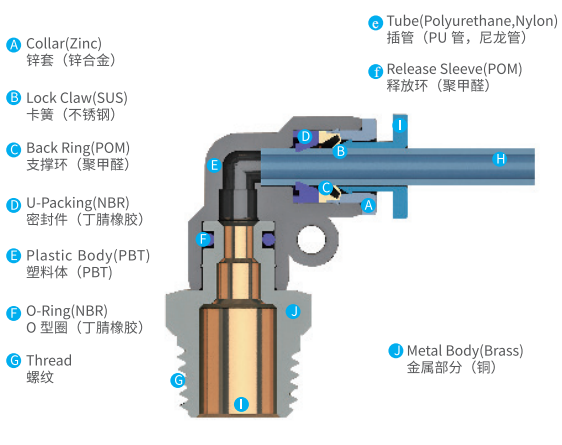
Seal interfaces
- O‑ring grooves:
- Standard and size: “O‑ring per ISO 3601, size 010 (ID/CS)”
- Groove dimensions: width, depth, diameter, squeeze (%), and gland fill
- Material: NBR 70 Shore for general air; FKM for high temp/oil mist; EPDM for oxygen
- Face seals:
- Specify flatness and roughness: “Sealing face flatness ≤ 0.05 mm; Ra ≤ 0.8 μm”
- Geometry control: perpendicularity/parallelism of sealing face to thread axis
- Push-to-connect ferrules/tubes:
- Tube OD and compatibility: “Ø8 mm PU/PA12 tube”
Materials and coatings
- Base material:
- Brass: CW614N (lead content for machinability), CW617N (for forged bodies)
- Stainless steel: 304 for general; 316/316L for food/pharma/corrosive media
- Aluminum: 6061‑T6 for lightweight manifolds/adapters
- Surface finish/coating:
- Nickel plating (electroless or electrolytic): e.g., 8–12 μm for corrosion resistance
- Zinc plating (clear/blue): economy option for non-corrosive environments
- Stainless steel passivation if required
- Anodizing for aluminum: specify type/color/thickness
- Cleanliness and media:
- “Components to be free of oil/particulate; suitable for dry air; food-grade optional (request documentation if required).”
Performance and test notes
- Pressure rating:
- Typical pneumatics: 10–16 bar; specify design and test pressures
- Leak test:
- “Bubble test at 6 bar in water for 30 s; no visible bubbles”
- Or air decay/pressure hold with defined limit
- Temperature range and environment:
- “–20 to +80 °C; dry compressed air; optional compatibility with mild oil mist”
Pro Tip: For export fittings, include a conversion note and 3D section view illustrating the seal path. Mislabeling BSPP vs. NPT is one of the most frequent causes of leakage in global shipments.
Which CAD formats (STEP, IGES, DWG) can my supplier accept?
Your drawing package should include both machine-readable geometry and a controlled print for notes and revisions.
Most Chinese CNC/turning suppliers accept STEP/IGES for 3D, DWG/DXF for 2D, and PDF for controlled notes. Provide a STEP file for solids, a fully dimensioned PDF, and optional native CAD if needed.
Preferred file formats
- 3D geometry:
- STEP (.stp/.step): best for neutral solid exchange; widely used in machining and CAM
- IGES (.igs): acceptable but older; prefer STEP where possible
- 2D manufacturing drawings:
- DWG/DXF: editable for CAM/programming; ensure units are clearly noted
- PDF: controlled release with title block, notes, tolerances, and revision history
- Native CAD (optional):
- SolidWorks (.sldprt/.sldasm), Inventor (.ipt/.iam), CATIA (export to STEP)
- File hygiene:
- State units (mm/inch) in both model and drawing
- Include revision, material, finish, and thread notes on PDF
- Avoid relying on model dimensions alone—always provide a print
Caution: Don’t let the 3D model be the single source of truth. Machinists will prioritize the PDF print for tolerances and notes; discrepancies between model and print delay production.
How should I mark critical dimensions and geometric tolerances on my print?
Your print should make it obvious which features control sealing, alignment, and assembly fit.
Key takeaway: Use GD&T to control thread axis alignment, sealing face flatness/roughness, and the position of ports. Apply general tolerances (ISO 2768-m or ASME Y14.5 defaults) to non-critical dimensions and highlight criticals with a delta or flag.
Critical features to mark
- Thread axis alignment:
- Perpendicularity of thread axis to sealing face: ⟂ 0.05 mm to datum A
- Sealing surfaces:
- Flatness: ⌧ 0.05 mm; surface roughness Ra ≤ 0.8 μm
- Concentricity or runout to thread axis if a concentric seal is used
- Port locations:
- Position tolerance: Ⓟ 0.10 mm to datums A|B|C for multi-port manifolds
- Bore diameters:
- Tight tolerances for push-in tube seats or spigot fits: e.g., Ø8 H7
- Chamfers and lead-in:
- Thread start chamfer (e.g., 45° × 0.5 mm) to prevent galling and ease assembly
General tolerance notes
- Linear/angular dimensions:
- “Unless otherwise specified: ISO 2768‑m (medium)”
- Fits:
- Use ISO 286 fit notation where applicable (e.g., Ø6 H7/g6 running fit)
- Surface finish:
- “Unspecified surfaces: Ra ≤ 3.2 μm; sealing faces: Ra ≤ 0.8 μm”
- Edges:
- “Break sharp edges 0.2–0.5 mm; deburr all threads and ports”
Example tolerance callouts (print excerpt)
- DATUMS: A = sealing face; B = external hex; C = thread axis
- FEATURE CONTROLS:
- Flatness ⌧ 0.05 to A
- Perpendicularity ⟂ 0.05 of thread axis to A
- Position Ⓟ 0.10 of port centerlines to A|B|C
- Total runout ⌰ 0.05 on external cylindrical sealing diameters
| Feature | Control | Typical Value | Rationale |
|---|---|---|---|
| Sealing face | Flatness + Ra | ⌧ 0.05 mm, Ra ≤ 0.8 μm | Leak-tight face seal |
| Thread axis | Perpendicularity | ⟂ 0.05 mm | Proper gasket seating |
| Port location | Position | Ⓟ 0.10 mm | Manifold alignment |
| External Ø | Fit | H7/g6 | Smooth assembly fit |
Pro Tip: Tag critical dimensions with a delta (Δ) or balloons linked to the inspection plan so QC knows what to measure 100% vs. by sampling.
What inspection plan should accompany my custom design submission?
A clear inspection plan aligns your quality expectations with supplier processes and prevents ambiguity during incoming inspection.
Provide sampling level (e.g., ANSI/ASQ Z1.4), characteristics to measure, thread gauge requirements, leak test method/pressure, and acceptance criteria. Include a first-article report and pre-shipment inspection checklist.
Inspection scope and sampling
- Sampling standard: ANSI/ASQ Z1.4 or ISO 2859‑1; define AQLs (e.g., 1.0 for critical, 2.5 for major)
- Critical characteristics (100% check):
- Thread standard verification with go/no-go gauges
- Sealing face flatness and roughness
- Bore diameters for tube seats
- Major characteristics (sampled):
- Port positions, overall length, hex size
- Plating thickness (XRF or coupon; e.g., nickel 8–12 μm)
- Minor characteristics:
- Cosmetic defects, chamfer presence, deburring
Test methods and acceptance criteria
- Dimensional inspection:
- Calibrated calipers, micrometers, bore gauges; CMM for GD&T features if specified
- Thread verification:
- Go/no-go gauges per standard (NPT, BSPP/BSPT, metric)
- Leak/pressure testing:
- Bubble test at 6 bar for 30 s (no bubbles) or air decay with max allowable drop
- Cleanliness:
- Visual inspection and wipe test; specify absence of chips/oil; add cleanliness class if needed
Documentation and checkpoints
- First Article Inspection (FAI):
- Supplier to submit FAI report with measured dimensions vs. nominal
- Include surface roughness readings for sealing faces
- Certificate of Conformance (CoC):
- Confirms material grade, plating spec, and thread standard compliance
- Pre-shipment inspection:
- Random sampling per AQL; dimensional and functional checks
- Packaging verification: caps/plugs on threads and ports, desiccant if needed
- Traceability:
- Lot numbers and revision control printed on labels
Caution: When customizing by physical sample, include your own measured dimensions and target nominals to avoid copying wear or drift from the legacy part.
Additional best practices for customizing pneumatic fittings from China
This section consolidates practical sourcing specifics that often reduce iterations and lead time.
Pair a clean drawing set with realistic tolerances and region-aware lead times. Clarify materials and finishes upfront, and run a first-article plus leak test before mass production.
Supplier regions and capabilities
- Ningbo, Wenzhou, Yuhuan: strong hubs for brass and stainless turned fittings, valves, and connectors
- Dongguan: CNC machining and precision components, good for stainless/aluminum prototypes
Lead time and MOQ
- Typical development:
- Quote: 3–7 days
- Samples: 2–4 weeks (faster for brass, longer for stainless with passivation)
- Mass production: 4–8 weeks post-FAI; MOQ depends on tooling and finish
Cost drivers
- Material: 316/316L > 304 > brass > aluminum
- Finish: Electroless nickel > electrolytic nickel > zinc
- Tolerance: Tight GD&T and roughness drive cycle time and inspection cost
- Threads: Multiple standards per part increase setups and gauge requirements
Material and application comparison
| Material Type | Typical Application | Pros | Considerations |
|---|---|---|---|
| Brass (CW614N/CW617N) | General pneumatics, manifolds | Affordable, easy machining | Avoid recycled brass; not for corrosives |
| Stainless 316/316L | Food & pharma, corrosive media | Corrosion-resistant, hygienic | Higher cost; longer machining/passivation |
| Stainless 304 | General industrial | Good corrosion resistance | Not as resistant as 316 in chlorides |
| Aluminum 6061‑T6 | Lightweight adapters | Fast machining, anodizing | Lower pressure threads; avoid aggressive media |
Pro Tip: For food-grade or cleanroom use, specify SS316/316L, electropolished or passivated surfaces, and document compliance expectations (e.g., material certificates, RoHS). Add a cleanliness note and packaging in sealed poly bags.
Conclusion: Turning a good idea into a manufacturable pneumatic fitting
Customizing pneumatic fittings by sample or drawing is straightforward when you control the essentials: thread standards (BSPP/BSPT, NPT, metric/ISO), seal interfaces (ISO 3601 grooves, face roughness), materials and finishes, and a practical inspection plan. Submit STEP/IGES for 3D, DWG/DXF for 2D, and a clear PDF print with ISO 2768‑m general tolerances and GD&T on critical features. Run a first-article with leak testing before mass production to lock in quality with Chinese pneumatic manufacturers.
Looking for reliable pneumatic component suppliers in China or help finalizing your drawing package? Contact us for a customized sourcing consultation.
