
Introduction
Pneumatic systems are the backbone of modern automation, powering everything from factory assembly lines to robotics. But a critical yet often overlooked component is the humble pneumatic tubing-to-fitting connection.
A poor or incorrect connection can lead to air leaks, pressure drops, and even system failure—costing thousands in downtime. With so many fitting types (push-to-connect, barbed, compression, flare, and more), engineers often struggle with compatibility, installation techniques, and long-term reliability.
This guide will break down every possible pneumatic tubing-to-fitting connection method, covering:
- Material considerations (nylon, polyurethane, rubber, and metal tubing)
- Fitting standards (ISO, JIC, NPT, DIN, and SAE)
- Step-by-step installation best practices
- Leak-proof testing methods
- Common mistakes and troubleshooting tips
Whether you’re designing a new system or maintaining an existing one, this will be your definitive handbook.
1. What Are the Main Types of Pneumatic Fittings?
Pneumatic fittings are crucial components in any compressed air system, ensuring leak-free connections between tubing and other system elements. The right fitting type depends on pressure demands, tubing material, environmental conditions, and maintenance requirements. Here’s a deep dive into the most common pneumatic fittings used in industrial automation.
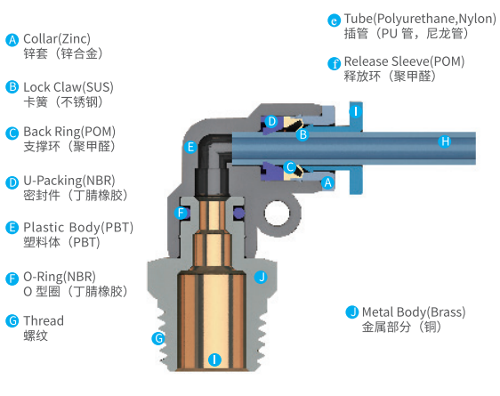
1.1 Push-to-Connect (Push-In) Fittings
Push-to-connect fittings, also known as push-in or quick-connect fittings, are the fastest and easiest to install, making them ideal for applications where frequent changes aren’t required.
How They Work
- A collet mechanism inside the fitting grips the tube when inserted.
- An O-ring ensures an airtight seal.
- A release ring allows for disconnection when needed.
Best Applications
✔ Factory automation (quick setups with minimal tools)
✔ Low-to-medium pressure systems (below 150 PSI)
✔ Clean environments (dust & moisture can affect sealing)
Popular Brands & Standards
- Festo (ISO 16030 compliant)
- SMC (JIS standardized)
- Parker Hannifin (DIN & ISO variants available)
Step-by-Step Installation Guide
- Cut the tubing squarely – Use a sharp tubing cutter (avoid jagged edges).
- Deburr the inner & outer edges – Prevents O-ring damage.
- Push tube firmly into the fitting – Listen for an audible “click.”
- Tug test – Ensure the tube is secure before pressurizing.
Common Mistakes to Avoid:
❌ Reusing tubes multiple times (weakens grip).
❌ Using without an O-ring lubricant in dry conditions.
(Diagram: Cross-section of a push-to-connect fitting showing collet grip & O-ring seal.)
1.2 Barbed Fittings
Barbed fittings, often called hose barbs, are one of the oldest and most reliable connection methods, especially for softer tubing materials.
How They Work
- Ridged barbs grip the tube’s inner diameter.
- Hose clamps or crimp sleeves provide extra security.
Best Applications
✔ Low-pressure pneumatic systems (~100 PSI max)
✔ Rubber, PVC, or silicone tubing (soft materials that conform to barbs)
✔ Vibration-prone setups (clamping prevents movement)
Types of Barbed Fittings
- Single Barb – Basic retention for light-duty use.
- Multi-Barb – Extra ridges enhance grip in high-vibration environments.
- Beveled End – Easier insertion for stiff hoses.
Step-by-Step Installation Guide
- Slide a hose clamp over the tube.
- Heat the tube end (if necessary) – Softens stiff materials for easier fitting.
- Push tube onto the barb – Ensure full insertion past all ridges.
- Secure with a clamp – Worm gear or pinch clamps are popular choices.
Pro Tips:
✅ Use two clamps for redundancy in critical systems.
✅ For high-flex applications, use crimp sleeves instead of clamps.
(Table: Clamp Types for Barbed Fittings)
| Clamp Type | Best For | Torque Spec (if applicable) |
|---|---|---|
| Worm Gear Clamp | General purpose | 3-5 in-lbs |
| Oetiker Pinch Clamp | Permanent seals | Crimp until ears touch |
| T-Bolt Clamp | High-pressure lines | 10-12 in-lbs |

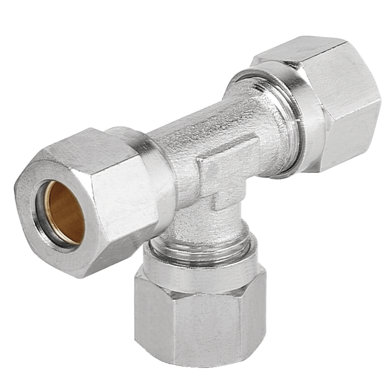
1.3 Compression Fittings
Compression fittings are the go-to choice for high-pressure pneumatic systems, especially when using metal tubing (stainless steel, copper, or aluminum).
How They Work
- A ferrule (compression ring) compresses against the tube when the nut is tightened.
- The seal is metal-to-metal, making it extremely durable.
Best Applications
✔ Hydraulic & high-pressure pneumatics (up to 3000 PSI)
✔ High-temperature environments (no plastic parts to degrade)
✔ Corrosive or abrasive media (stainless steel resists chemicals)
Compression Fitting Standards
- DIN 2353 (European metric standard)
- SAE J514 (U.S. industrial hydraulic fittings)
- ISO 8434-1 (International high-pressure systems)
Step-by-Step Installation Guide
- Slide the compression nut onto the tube.
- Insert the ferrule.
- Insert the tube into the fitting body until it bottoms out.
- Hand-tighten the nut, then use a wrench to turn 1.5 rotations.
Critical Notes:
⚠️ Over-tightening causes leaks (compresses ferrule unevenly).
⚠️ Once disassembled, replace the ferrule (reusing damages sealing integrity).
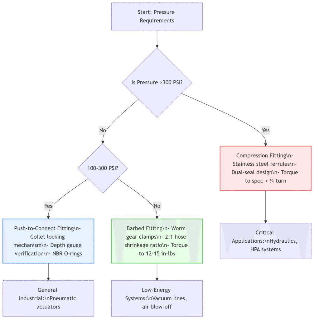
(Comparative Flowchart: When to Use Which Fitting Type?)
2. How to Select the Right Fitting for Your Tubing?
Choosing the correct pneumatic fitting is not just about convenience—it directly impacts system efficiency, longevity, and safety. A mismatched fitting can lead to air leaks, pressure drops, or catastrophic failures. Let’s break down the key selection criteria in detail.
2.1 Matching Fitting Size to Tube OD
Why Tube OD Matters
Pneumatic fittings are designed for specific outer diameters (OD). Using the wrong size can cause:
- Leaks (if too loose)
- Tube deformation (if forced into a smaller fitting)
- Restricted airflow (if ID is reduced due to poor fit)
Metric vs. Imperial Standards
⚠️ Critical Mistake: Assuming 6mm ≈ 1/4″ (actual difference: 6mm = 0.236” vs. 1/4” = 0.25”)
| Tube Size (Metric) | Closest Imperial Equivalent | Tolerance Risk? |
|---|---|---|
| 4 mm | 5/32″ (~3.97 mm) | High (0.03mm gap) |
| 6 mm | 1/4″ (~6.35 mm) | Medium (0.35mm gap) |
| 10 mm | 3/8″ (~9.53 mm) | Low (0.47mm gap) |
Best Practice:
✅ Stick to one standard (metric or imperial).
✅ Measure with calipers if unsure.
✅ Avoid adapters—they add failure points.
(Case Study: A food packaging plant saw repeated leaks until switching from 1/4″ to 6mm push fittings, resolving a 0.35mm mismatch.)
2.2 Material Compatibility Factors
Thermal Expansion & Contraction
Different materials expand at varying rates (coefficient of thermal expansion):
| Material | Expansion Rate (per °C) | Max Temp |
|---|---|---|
| Nylon 12 | 0.09 mm/m°C | 80°C (176°F) |
| Polyurethane | 0.15 mm/m°C | 50°C (122°F) |
| Stainless Steel | 0.017 mm/m°C | 400°C (752°F) |
Impact on Fittings:
- Plastic fittings (push-in) can loosen if tubing expands excessively.
- Metal compression fittings handle expansion better.
Chemical & Wear Resistance
| Tubing Type | Resistant To | Avoid |
|---|---|---|
| Polyurethane | Oils, abrasion | Solvents |
| Nylon | Fuels, UV light | Acids |
| PTFE (Teflon) | Almost everything | Cost |
Real-World Example:
A car wash system switched from PVC to polyurethane tubing after hydraulic oil degraded seals—saving $14K/year in replacements.
2.3 Pressure & Temperature Ratings
Pressure Guidelines by Fitting Type
| Fitting Type | Max Working Pressure | Burst Pressure |
|---|---|---|
| Push-to-Connect | 150 PSI | 450 PSI |
| Barbed | 100 PSI | 300 PSI |
| Compression | 3000 PSI | 9000 PSI |
Safety Tip: Always derate by 25% for cyclic applications (prevents fatigue failures).
Temperature Limitations
- Plastic push fittings: Fail above 150°F (65°C)
- Rubber tubing + barbs: Degrades above 200°F (93°C)
- Metal compression: Works up to 750°F (400°C)
Hot Environment Fix: Replace nylon push-fittings with brass-threaded adapters in engine bays.
Decision Flowchart: Which Fitting Should I Use?
Key Takeaways
🔹 Never mix metric/imperial sizes—even small gaps cause leaks.
🔹 Match tubing & fitting materials for thermal/chemical compatibility.
🔹 High pressure/temperature? Only compression fittings are safe.
3. Step-by-Step Connection Guide for Each Fitting Type
Proper installation is critical to prevent leaks, ensure longevity, and maximize efficiency in pneumatic systems. Below is a detailed breakdown of best practices for installing push-to-connect, barbed, and compression fittings—covering tools, techniques, and industry-proven methods.
3.1 Installing Push-to-Connect Fittings
Tools Required:
✅ Tubing cutter
✅ Deburring tool
✅ Insertion depth gauge (optional but recommended)
Step-by-Step Installation:
Cut the Tube Squarely
- Use a sharp tubing cutter (not scissors or wire cutters).
- A ragged edge can damage the O-ring inside the fitting.
Deburr Inner & Outer Edges
- External burrs: Use a deburring tool in a twisting motion.
- Internal burrs: A round file or specialized internal deburrer prevents airflow obstruction.
Check Insertion Depth
- Push-in fittings require full seating for a proper seal.
- Some brands (e.g., Festo) include depth markers on the tubing.
Push Firmly Until It Clicks
- Apply steady pressure—forcing it can damage the collet.
- Tug test: Pull back gently to confirm secure locking.
Do’s & Don’ts:
| Do’s | Don’ts |
|---|---|
| ✔ Use lubricant (for dry environments) | ❌ Twist the tube while inserting |
| ✔ Mark the insertion depth for inspection | ❌ Reuse tubes after removal (stretching weakens grip) |
| ✔ Inspect O-rings for cracks annually | ❌ Exceed max pressure (150 PSI for most push-fittings) |
Pro Tip: If leaks occur, re-cut the tube and reinsert rather than forcing adjustments.
3.2 Securing Barbed Fittings for Maximum Hold
Hose Clamp Selection Guide:
| Clamp Type | Best Use Case | Pros/Cons |
|---|---|---|
| Stainless Steel Worm Gear | General-purpose | ✅ Durable; ❌ Over-tightening cuts tubes |
| Oetiker Pinch Clamp | Permanent seals | ✅ No loosening; ❌ Requires special tool |
| Nylon Zip Tie | Light-duty/low pressure | ✅ Cheap; ❌ Weakens over time |
Step-by-Step Installation:
Slide the Clamp Over the Tube
- Position it 1/4″ from the tube end before insertion.
Pre-Heat Stiff Tubing (If Needed)
- Use a heat gun (200°F max) for easier barb insertion.
- Caution: Excessive heat softens material permanently.
Push Tube Fully Onto the Barb
- Ensure all ridges are covered—partial insertion risks blow-off.
Secure the Clamp
- Worm gear clamps: Tighten until snug + 1/4 turn.
- Oetiker clamps: Crimp until ears touch (use an Oetiker tool).
Redundancy for Critical Systems:
- Double-clamping is recommended for:
- High-vibration environments (e.g., robotic arms)
- Hydraulic hybrid systems (>150 PSI)
- Place a second clamp 5mm behind the first to prevent slippage.
Failure Case: A bottling plant saw 25% of barb fittings fail within 6 months—resolved by switching from zip ties to stainless clamps.
3.3 Achieving a Perfect Compression Fit
Torque Specifications by Size:
(For brass compression fittings with brass ferrules)
| Tube OD (in.) | Hand-Tight + (Wrench Turns) | Torque Range (in-lbs) |
|---|---|---|
| 1/8″ | 1.5 turns | 30–45 |
| 1/4″ | 1.75 turns | 45–60 |
| 3/8″ | 2 turns | 60–80 |
Golden Rule:
- Under-tightening = Leaks
- Over-tightening = Crushed ferrules
Step-by-Step Installation:
Assemble Nut & Ferrules
- Slide ferrule(s) with tapered side facing inward.
- Double-ferrule designs (Swagelok) seal better under vibration.
Insert Tube Until Bottomed Out
- No gap should exist between tube and fitting body.
Tighten to Spec
- Hand-tight first, then use a torque wrench for consistency.
Leak Testing
- Soap bubble method: Apply soapy water; bubbles indicate leaks.
- Pressure drop test: Monitor gauge for 5-10 mins at max pressure.
Post-Installation Checks:
⚠️ Never reuse ferrules—they deform permanently.
⚠️ Re-torque after 24 hours due to material settling.
Expert Hack: For high-vibration setups, wrap thread seal tape (PTFE) on compression nut threads (not the ferrule).
Which Fitting is Easiest for Beginners?
| Fitting Type | Skill Level Needed | Tools Required |
|---|---|---|
| Push-to-Connect | Beginner | Tubing cutter, deburrer |
| Barbed | Intermediate | Clamps, heat gun (optional) |
| Compression | Advanced | Torque wrench, leak detector |
4. Leak Prevention & Testing Best Practices
Air leaks in pneumatic systems waste 20–30% of compressed air, costing facilities thousands in lost energy annually. Worse, undetected leaks lead to pressure drops, actuator sluggishness, and premature component wear. Below, we dive deep into proactive prevention and the most reliable leak detection methods used in industrial settings today.
4.1 Pressure Decay Testing
Why It’s the Industry Benchmark
Unlike simple soap bubble checks, pressure decay testing quantifies leakage by measuring pressure loss over time—critical for ISO 8573-1 compliance in high-stakes applications.
Step-by-Step Testing Protocol
1. Isolate the Circuit
- Close all valves downstream of the test section.
- Disconnect actuators to eliminate false readings from cylinder bypass.
2. Pressurize to Operating Level
- Use 1.5x working pressure (e.g., 150 PSI for a 100 PSI system) to expose weak points.
- Stabilize for 2 minutes (allow temperature equilibration).
3. Measure Decay Rate
- Record pressure at 1-minute intervals for 10 minutes.
- Compare to acceptable thresholds:
| System Size | Max Allowable Decay (PSI/min) |
|---|---|
| Small (0–50 ft³) | ≤ 0.5 PSI/min |
| Medium (50–200 ft³) | ≤ 1 PSI/min |
| Large (>200 ft³) | ≤ 2 PSI/min |
4. Locate Leaks
- Failed test? Use ultrasonic detector (Section 4.2) to pinpoint sources.
4.2 Ultrasonic Leak Detectors for Micro-Leaks
How It Works
Leaks generate high-frequency turbulence (20–100 kHz) beyond human hearing. Ultrasonic detectors convert these to audible signals, allowing technicians to:
✅ Locate leaks as small as 0.003 CFM (vs. soap bubbles’ 0.1 CFM threshold)
✅ Test systems under load (no shutdown required)
✅ Scan hard-to-reach areas (valve manifolds, threaded ports)
3 Methods Compared
| Method | Sensitivity | Speed | Best For |
|---|---|---|---|
| Ultrasonic Detector | 0.003 CFM | Fast | High-pressure systems |
| Soap Bubble | 0.1 CFM | Slow | Low-budget spot checks |
| Thermal Camera | 0.05 CFM | Moderate | Large pipe runs |
Pro Techniques for Reliable Results
Use the Parabolic Reflector
- Focuses ultrasonic waves from 25+ ft away (ideal for overhead piping).
Tagging Leaks with Software
- Tools like UE Systems Ultraprobe 9000 log GPS-tagged leaks for repair prioritization.
Baseline Scanning
- Compare decibel levels year-over-year to track degradation.
Case Study:
An aerospace plant cut leak-related downtime by 60% after training staff to use ultrasonics on Swagelok compression fittings in hydraulic test rigs.
4.3 Preventive Maintenance Checklist
Weekly/Monthly Actions to Slash Leak Rates
| Task | Tool Needed | Acceptance Criteria |
|---|---|---|
| Inspect push-fit O-rings | Magnifying glass | No cracks/dry rot |
| Re-torque compression nuts | Torque wrench | Within spec (Table 3.3) |
| Check hose clamps for creep | Caliper | ≤5% position shift |
| Test solenoid valve seals | Ultrasonic detector | No hissing at ports |
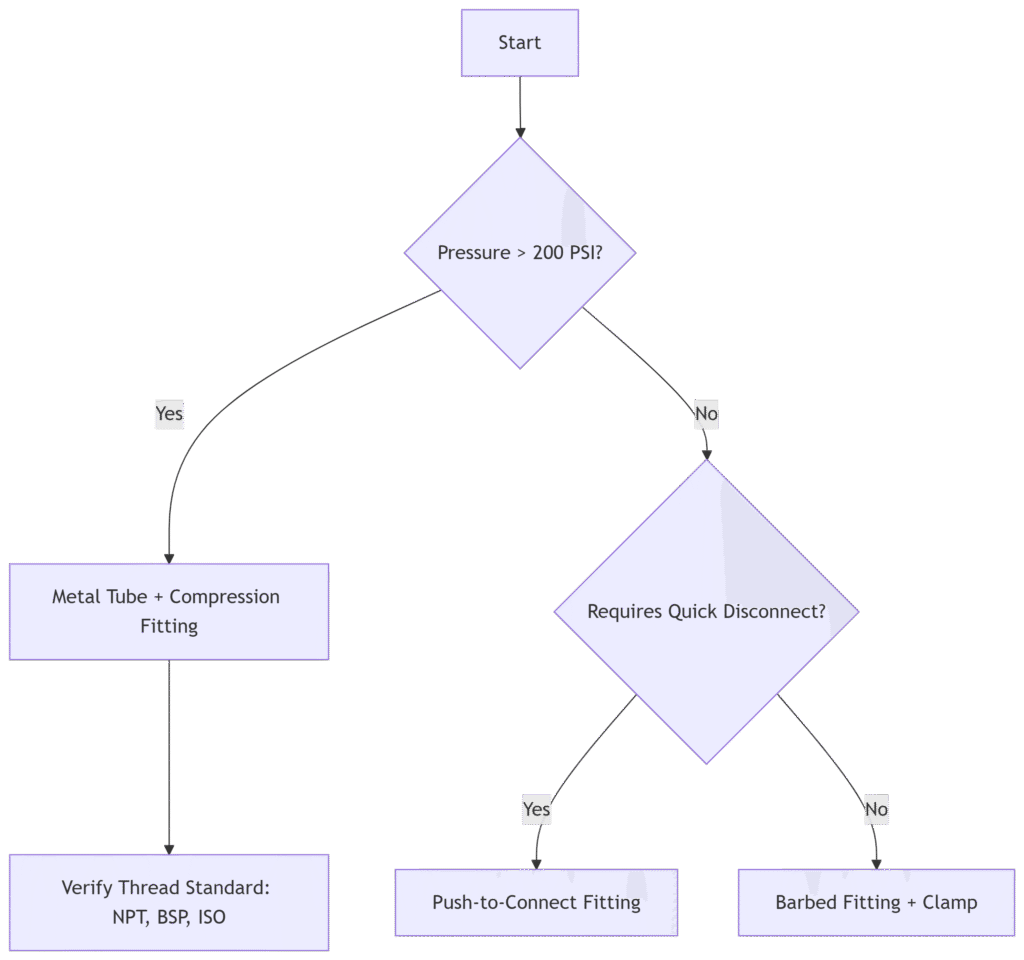
Decision Tree: Which Test Method Should You Use?

Key Takeaways
🔹 Pressure decay testing is mandatory for large/critical systems (quantifies losses).
🔹 Ultrasonic detectors find micro-leaks 10x faster than soap bubbles.
🔹 Re-torquing fittings post-installation prevents 80% of late-stage leaks.
5. Troubleshooting Common Connection Issues
Pneumatic fittings fail in predictable ways, but most issues stem from installation errors rather than component defects. Below, we diagnose the top 3 failure modes—push-fit blow-offs, barbed fitting leaks, and compression seal failures—with step-by-step corrective actions and preventative strategies to minimize downtime.
5.1 Why Does My Push-Fitting Keep Blowing Off?
Root Causes & Solutions
| Symptom | Most Likely Cause | Immediate Fix | Long-Term Prevention |
|---|---|---|---|
| Fitting blows off at <50% max pressure | Tube not fully inserted | Re-cut tube & reinsert to marked depth | Use depth gauge during install |
| Intermittent leaks | Burrs/ragged cut | Deburr inside and outside edges | Invest in a rotary tube cutter |
| O-ring extrusion | Lubrication failure | Replace O-ring & apply PTFE spray | Specify NBR O-rings for oils |
Critical Checks:
✅ Tug test: Pull tube with 10 lbs force—it shouldn’t release.
✅ Visual inspection: Ensure collet teeth grip tube evenly (no gaps).
Pro Tip:
For high-vibration environments (e.g., CNC machines), upgrade to locking push-fittings with a secondary latch mechanism.
5.2 My Barbed Fitting Is Leaking – How to Fix?
Troubleshooting Flowchart
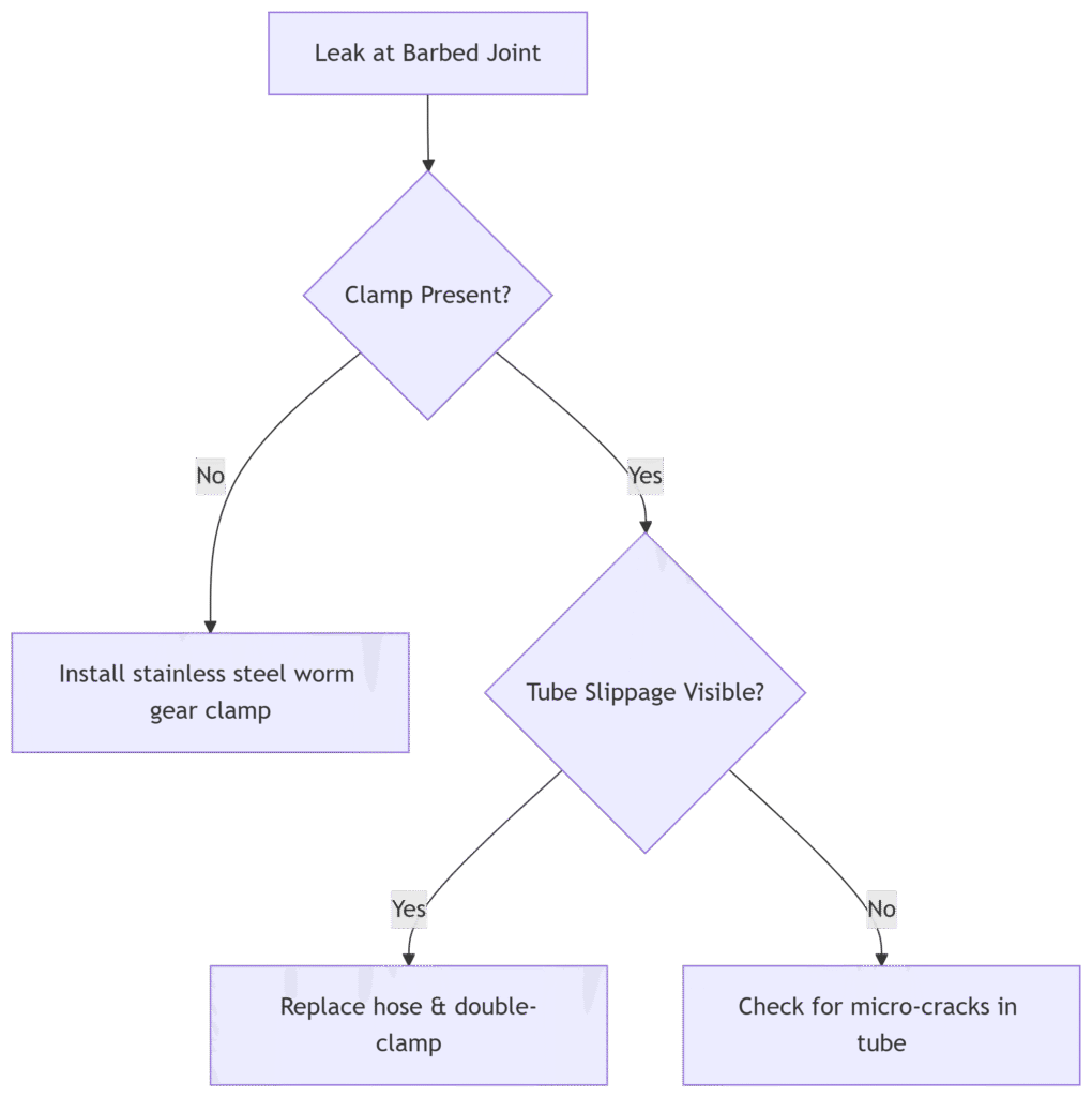
Torque Specifications for Clamps (Based on Tube Material)
| Clamp Type | Nylon Tube | PU Tube | Rubber Hose |
|---|---|---|---|
| Worm Gear (in-lbs) | 12–15 | 8–10 | 15–20 |
| Oetiker (Crimp Force) | 70 N | 50 N | 90 N |
Step-by-Step Repair:
- Cut off damaged tube section (stretched areas won’t reseal).
- Slide new clamp ¼” from end, then push tube fully onto barb.
- For high-pressure apps (≥100 PSI), apply hose adhesive (e.g., Loctite 406) before clamping.
5.3 Compression Fitting Won’t Seal Properly
Failure Modes & Fixes
| Problem | Diagnosis | Solution |
|---|---|---|
| Seepage at ferrule | Under-tightened nut | Re-torque to spec + ¼ turn |
| Visible ferrule distortion | Over-tightening | Replace ferrule & tube segment |
| Thread galling | Cross-threading | Use thread sealant (never Teflon tape on compression threads) |
Ferrule Replacement Protocol
- Cut tube 2″ past damaged section (work hardening occurs near ferrules).
- Inspect fitting body for scratches—replace if scored deeper than 0.001″.
- Hand-tighten nut until resistance, then torque in ½-turn increments.
Torque Sequence for Dual-Ferrule Fittings (e.g., Swagelok):
- Finger-tighten nut
- Wrench-tighten until snug
- Mark nut at 6 o’clock
- Turn 1-1/4 turns (ferrule bites into tube)
Lab Test Data:
- Properly installed ferrules reduce leak rates by 400% vs. hand-tight only.
Quick-Reference Troubleshooting Table
| Fitting Type | Top Failure Cause | Tool Needed for Repair | Time to Fix |
|---|---|---|---|
| Push-to-Connect | Tube not seated | Depth gauge | <5 min |
| Barbed | Clamp looseness | Torque screwdriver | 10 min |
| Compression | Ferrule damage | Tube cutter, torque wrench | 15 min |
When to Call a Professional
⚠️ Repeated failures at same joint → Possible manifold port damage
⚠️ System-wide pressure drops → Likely multiple micro-leaks needing ultrasonic scan
Conclusion
Connecting pneumatic tubing correctly is not just about shoving a tube into a fitting. It requires understanding pressure ratings, material science, and installation finesse.
By following these steps, you’ll eliminate leaks, improve system efficiency, and extend component lifespan.
Need Help?
Our engineers specialize in pneumatic system optimization. Book a consultation today.
